Spectroscopic and continuum maps can be obtained with a series of single pointings using the spacecraft raster mode. A map can contain one scan (one-dimensional mapping) or several scans (two-dimensional mapping). All pointings of a raster map must lie within an area of 1.5 by 1.5 square degrees. Mapping will be available for CAM, PHT and LWS. The observer has to specify the coordinates of the centre position, the number of scan lines (N), the number of points in a scan line (M) and the step sizes in arcsec. The latter are: the distance between the scan lines and the distance between points in the scan line. Additionally, the observer specifies the position angle of the scan lines i.e. the orientation of the map (see Fig. 11).
The number of points in a scanline and the number of scanlines can be any integer between 1 and 32. Setting one of the numbers to 1 specifies a one-dimensional scan. Allowed step sizes are: 0,2,3,...,180 arcsec.
For SWS, a map is not defined as described above, but the observer specifies the map by giving for each point the coordinates and concatenating the observations in the map (see also 13.4).
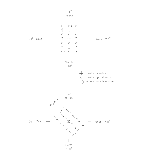
Figure 11: Mapping with ISO. The upper panel shows the sampling procedure for an orientation angle of 0~degrees. The number of scanlines is 3, the number of points in a scanline is 4. The lower panel illustrates the map, with the same mapping parameters as above, but with an orientation angle of 47~degrees. The start position of the map is indicated by the filled circle.
The orientation angle of a map or a scan is counted from the North direction via East (see Fig. 11). The values for the orientation angle can be between 0 and 179 degrees. Note that to obtain a scan in East-West direction, the scan orientation angle has to be set to 90 degrees.
The map parameters are specified with respect to the equatorial coordinate system (Right Ascension and Declination for a given epoch). The orientation of the spacecraft axes is essentially arbitrary with respect to that system. Since the orientation of the detector arrays (i.e. CAM and PHT-C) and rectangular apertures (for PHT-P) is fixed with respect to the spacecraft axes, the orientation of the array or aperture with respect to the scan line is arbitrary. More details can be found in the CAM and PHT OBSERVER'S MANUALS. In case an alignment of the axes of a map in Right Ascension and Declination with the spacecraft axes is desired for observations with the detector arrays, observers should consider to use the spacecraft coordinate system instead of the equatorial system. This is only of concern during Phase 2 data entry.
For scheduling, mapping is regarded as a single observation. Thus, a map, or a scan, will only be scheduled as a whole or not at all.
The overhead to start a map observation is 180 sec. Additional overheads accumulate due to moving from one point to the next one. The slews between points in a map are usually much shorter than the slews for target acquisition. In contrast to the latter, these slews involve the same guide star and the control is different. They are called micro-slews.
In the following a procedure is described how to calculate the overhead due to these micro-slews.
The acceleration to the maximum speed and the deceleration to slow down to
zero is 3 seconds each, the maximum slewing speed, called the coasting speed,
within a map is ![]() arcsecsec
arcsecsec ![]() .
The acceleration and deceleration is a +/- 6.67 arcsecsec -2 ,
which leads to a threshold distance of
.
The acceleration and deceleration is a +/- 6.67 arcsecsec -2 ,
which leads to a threshold distance of ![]() arcsec, at which
the coasting speed is reached, The minimum distance, or step size, for
micro slews is 2 arcsec though individual instruments may place
additional constraints on this spacecraft specification.
arcsec, at which
the coasting speed is reached, The minimum distance, or step size, for
micro slews is 2 arcsec though individual instruments may place
additional constraints on this spacecraft specification.
To calculate the total overhead for micro slews within a map, first the
time to slew between points has to be determined. In case the step
sizes between points in a scan line and between scan lines is not the same
the times have to be calculated for each individually, ![]() and
and
![]() .
In a second step, the number of slews between points in all scan lines and
between scan lines has to be determined and multiplied with the respective
time per slew.
.
In a second step, the number of slews between points in all scan lines and
between scan lines has to be determined and multiplied with the respective
time per slew.
For a step size smaller than 60 arcsec, i.e. twice ![]() ,
,
and accordingly for ![]() .
.
For a step size larger than 60 arcsec the path ![]() is slewed with
is slewed with ![]() . The time for the slew is then
. The time for the slew is then
For a step size of 60 arcsec obviously ![]() sec.
sec.
Let N be the number of scan lines and M
be the number of points in a scan line
then the number of slews between scan lines is N-1 and the number of
slews between all points in N scan lines is ![]() .
The overhead for micro slews
.
The overhead for micro slews ![]() is then:
is then:
In case the step sizes ![]() and
and ![]() are equal the
equation reduces to:
are equal the
equation reduces to:
Examples:
For the examples the map illustrated in Fig. 11 shall be taken. The map has 3 scan lines and 4 points in each scan line.
1. In the first example let the step sizes be equal: ![]() . The step size is smaller than 60 arcsec thus
Equ. (5) applies:
. The step size is smaller than 60 arcsec thus
Equ. (5) applies:
![]()
Note that the value obtained for the square root has to be rounded to the next higher integer.
Since the step sizes are equal ![]() becomes (see
Equ. 8):
becomes (see
Equ. 8):
![]()
2. In the second example let the step sizes be different,
![]() and
and ![]() .
Both are larger than
.
Both are larger than ![]() . Here, Equs. (6) and
(7) apply.
. Here, Equs. (6) and
(7) apply.
For ![]() the slew time is
the slew time is
![]()
and for ![]()
![]()
Note that the value obtained for ![]() has to be rounded to the next higher integer.
has to be rounded to the next higher integer.
For ![]() one obtains then:
one obtains then:
![]() sec
sec