The Next-Generation Infrared Astronomy Mission
![]()
![]()
Instruments onboard SPICA
SPICA’s Infrared Eyes
Home > Instruments onboard SPICA
Large-aperture Cryogenic Telescope
SPICA will employ a 2.5 m diameter Ritchey-Chretien telescope with a field of view of 30 arc minutes, whose mirror is polished to achieve the diffraction limit at the wavelength of λ = 20 μm. The entire telescope will be kept cooled to below 8 K (-265 ℃) during observations to decrease its own infrared radiation and thus achieve high sensitivity.
This large telescope is required to be lightweight. To obtain clear images, the telescope also needs to be made of a material having small distortion. Hence as the material for the telescope, SPICA will adopt light and tough Silicon Carbide (SiC), which has been successfully used in previous missions such as AKARI and Hershel. Thus, despite the largeness of the telescope, its total mass is estimated to be no more than about 600 kg.
ESA (The European Space Agency) is responsible for development of the telescope.
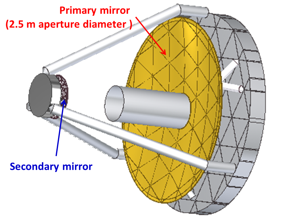
Fig. 1 Schematic view of the SPICA telescope assembly
Focal Plane Instruments
The following two focal plane instruments will be onboard SPICA:
the SMI (SPICA Mid-Infrared Instrument) and the SAFARI (SpicA FAR-infrared Instrument).
SPICA Mid-infrared Instrument; SMI
A number of dust band emissions are found in the mid-infrared range (e.g., λ = 20 - 40 μm). Among these, observations of nearby galaxies have shown that band emissions from PAH (Poly-Aromatic Hydrocarbon) dust are an indicator of star formation activity. In spite of this importance, a high-sensitivity observation in the mid-infrared band has yet to be performed.
The SMI covers the wavelength range from 12 to 36 μm with four separate channels: three spectrometers (LR, MR, and HR) and one imager (CAM) with a highest sensitivity. SMI is the Japanese-led instrument proposed and managed by a nation-wide consortium in Japan and will be developed in collaboration with Taiwan and the US.
* See "SPICA/SMI website" (also see "For Astronomer") for the latest information on the SMI performance.
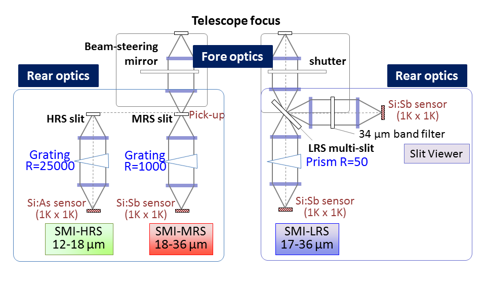
Fig. 2 Block diagram of the basic functions of SMI
SPICA Far-infrared instrument; SAFARI
The SAFARI is a diffraction grating spectrometer designed to achieve the highest-ever sensitivity for line emission in the wide far-infrared wavelength range of λ = 34 - 210 μm (TBD) with a moderate wavelength resolution (R=300). The SAFARI will employ a TES (Transition Edge Sensor) bolometer developed by SRON (Netherlands Institute for Space Research) as a far-infrared detector. An additional function enabling high-resolution observations (R=3,000) by a combination of a Fabry‐Perot interferometer with the diffraction grating is under consideration. With its beam steering mirror, it can perform imaging observations of a 2 arc minute square region on the sky. This function is effective to observe diffuse celestial objects. The SAFARI Consortium consisting of institutes/universities from Europe, Canada and U.S.A is responsible for development of the SAFARI.
In the SAFARI wavelength range, there are various bright emission lines from ionized gas. With its high sensitivity, the SAFARI can reveal star formation history in galaxies and evolution of supermassive black holes at their center, by detecting these emission lines from distant galaxies.
* See "For Astronomers" for the latest information on the SAFARI performance.
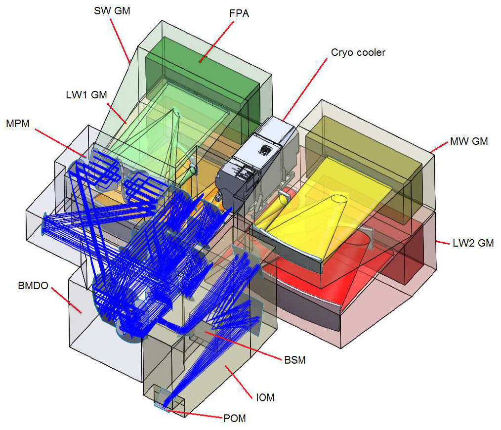
Fig. 3 Overview of SAFARI Cold Unit
-265 ℃, What a Cool Telescope !
Because every object emits infrared radiation at a wavelength corresponding to its temperature, infrared emission from the telescope itself can be a serious hindrance to high sensitivity observations. To overcome this issue, SPICA will cool its entire telescope to -265 ℃ (8 K) with a sophisticated cryogenic technology, which enables unprecedented sensitivity in the mid-to-far infrared wavelength range. Being capable of making observations of more distant galaxies with this cool telescope, SPICA is expected to reveal a completely new side of the Universe.

Fig. 1 Comparison of pictures taken in visible (left) and infrared (right) bands. The right hand warmed with hot water looks bright, while the left hand cooled with iced water looks dark in the infrared picture; warmer objects emit stronger infrared radiation than cooler objects.
Observation from the L2 point
To keep a telescope cool, it is necessary to reduce heat influx from both the Earth and the Sun to the maximum extent. To perform high sensitivity infrared observations without being affected by the atmosphere of the Earth, observing from space is absolutely necessary.
From these considerations, SPICA opts for a halo orbit around the second Lagrangian point (L2) <*1> of the Sun-Earth system as its observation point. At the L2 point, 150 million km away from the Earth, the heat flux from the Earth is relatively small. Additionally, at the L2 point, it is possible to simultaneously insulate the spacecraft from both the Earth and the Sun, because at the L2 point the Sun and the Earth are in almost the same direction.
SPICA will be the first Japanese space observatory to be launched into the L2 point. The launcher is planed to be the H3 Launch Vehicle, the next flagship rocket of JAXA, which is capable of carrying this huge observatory out to the L2 point.
*1: the Lagrangian points: At these points, the gravity from the Sun and Earth are balanced with the centrifugal force of the orbiting satellite.
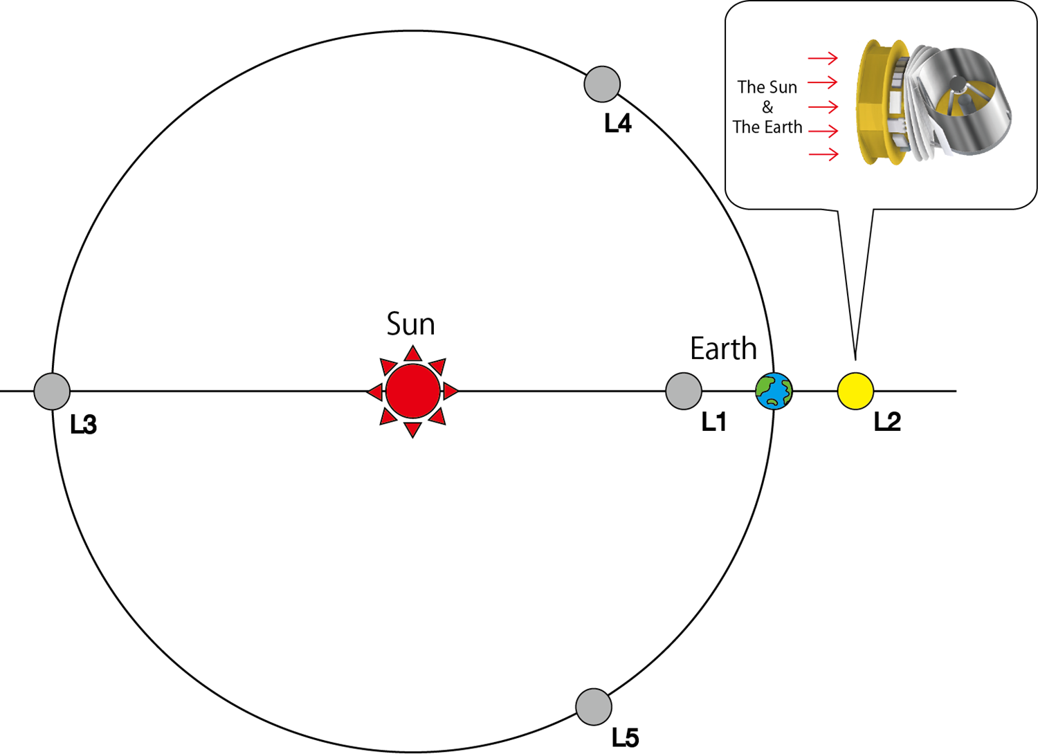
Fig. 2 Schematic view of the Lagrangian points (L1-L5) of the Sun-Earth system. SPICA is to be launched into the L2, which is located 150 million km away from the Earth on the opposite side from the Sun.
Mechanical Cryocoolers; the Japanese Innovative Technology
Liquid helium has been commonly used as a cryogenic refrigerant for telescopes and instruments onboard scientific satellites. To carry liquid helium into space requires a large tank, which makes satellites larger and heavier, and hence restricts their telescope size. Moreover, cryogenic duration is limited by the mount of liquid helium.
To eliminate these obstacles, SPICA will employ innovative mechanical cryocoolers, instead of conventional liquid-helium. This allows SPICA to realize a 2.5 m large aperture telescope with an optical throughput 10 times higher, and a designed life time (3 years) longer than those of AKARI.
The SPICA cryogenic system adopts two kinds of Joule-Thomson refrigerators (the 1K and 4K classes) with a world-best cooling power. These mechanical coolers are developed by the Research and Development Directorate of JAXA. The same types of coolers were adopted by the X-ray observatory Hitomi (previously known as ASTRO-H), and are to be onboard the cosmic background radiation observatory, LiteBIRD. This mechanical cooler technology is a key technology for successful space satellites.
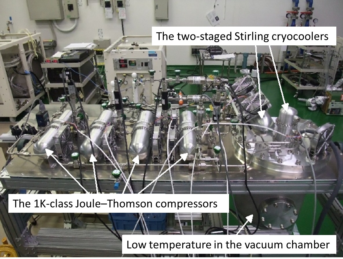
Fig. 3 The 1K-class Joule-Thomson refrigerator developed by JAXA
(Sato et al 2015),
coupled with a two-stage Stirling cryocooler for precooling.
V-groove Thermal Shields
To cool the entire telescope, it is also important to block heat form the sun and instruments onboard, in addition to direct cooling. Hence, as a strategy for heat insulation, SPICA will adopt V-groove thermal shields<*2>, which were used in Plank observatory developed by ESA.
The V-groove thermal shields are sunshades bent in a V-shape. In the configuration of SPICA, triple-layer V-groove thermal shields will be arranged between the service module and the telescope (see Fig. 4) to enable effective insulation by letting heat from the sun, the earth and the service module into space. Being closer to the telescope, the temperatures of the shields will be lower. This mechanism allows the telescope and the focal plan instruments to be cooled to cryogenic temperatures.
<*2> See information on the Planck thermal design at the Planck web
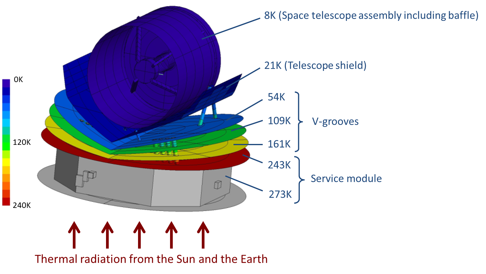
Fig. 4 Structural-thermal design of SPICA currently under study. The triple-layer V-groove thermal shields protect the telescope from thermal conduction from the sun, the earth and the service module. (Based on the study report of Next Generation-Cryogenic cooled Infrared Telescope compiled by the ESA's Concurrent Design Facility (CDF))